Table of Contents
Architectural Model
Micromouse Architecture
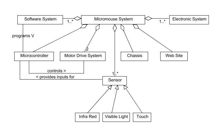
The UML class diagram below is a very high-level (architectural) model of the Micromouse Project. It is based on the initial discussions that we have had in project planning and team building phases. This diagram is not necessarily complete. For example, not all subsystems are necessarily present, and only a few associations have been added to model the relationships between subsystems. It is however at about the limit, in terms of information content, that one person can take in at a glance.
To further explore the structures represented by the high-level subsystems, further refinement will be necessary. For example, you may find that the motor drive system is made up of a DC motor, gearbox, tachometer (measures angular velocity), and motor drive electronics driven by a PWM output signal from the microcontroller. Similar “aggregations” will exist for other sub-systems. To keep things understandable, we suggest that you model these sub-divisions by creating additional diagrams, rather than extending this one.
How much detail is needed?
To answer this question, it is perhaps important to remember that UML class diagrams are intended to help you to identify and communicate the classes, attributes, and associations that will be present in your system. This needs to be done in sufficient detail that you can identify the components that need to be built, define the interactions between these components, allocate tasks to team members, and identify which team members will need to communicate with each other. However, they do this best if each individual diagram is kept as simple as possible! Remember the Magical Number Seven!
How should we initially model our system?
Ideally, the initial high-level (architectural) modeling is something you will work on and complete as a team. Probably at a white board, black board or a flip-chart rather than sitting at a computer. You will find that it is not necessary to model every single detail, your aim is to gain a high-level understanding of the project and how it is to be divided up, and communicate that understanding to each of your team members. Having done this you will be in a better position to decide, and agree on what is to be done in the remaining time on the project and by whom.
Do we have to use a tool?
It is not necessary to use a modeling tool. Once you have agreed it, you will need to store a hard copy of your model(s) in your project documentation repository. However, you do not necessarily need to produce this hard copy with a computer. A hand drawn sketch, scanned and uploaded to the web site, is perfectly acceptable provided that it is readable and records the information that you have agreed with others in your team. Remember that UML is supposed to be a language, and it can be written in any medium that helps you communicate quickly and efficiently. If you find that the tools available, hinder this communication, don't use them! Having said that, the model shown here was drawn in UMLet, a simple tool for UML diagramming, that you'll find on the School's network (under Software Engineering). It took me a fraction of the time to draw this picture as it took me to type this commentary! You can download the file that produced this diagram from the Blackboard site and use it as a starting point for refinement if you wish. You may find that UMLet is a very good for converting sketches into reasonably good looking diagrams that you can use in other documents.
Will more modeling be required?
Yes! Dr Holt will explain how UML models can be used as an aide to project planning and project management. Furthermore, as you start to work on your individual tasks within the project, you will find it useful to create additional models to help you to think about, design and communicate your designs to others in your team and your assessors. Generally, any such generated models should be made available on your team web site. Additional model types that you might consider using would include use-case diagrams, Gantt charts, circuit diagrams, class and object diagrams, activity diagrams, state-charts, sequence diagrams, block diagrams, flow charts, sensor graphs, etc. It is worth pointing out that only five or six of these model types is actually a UML diagram!
How do I obtain a copy of UMLet for use at home?
It's worth noting that the UMLet tool is an open source Java application that you can download from www.umlet.com and install on your own PC. You will need to have installed either the SDK for the Java 5 Standard Edition, or the version 5 Java run-time environment (JRE) on your PC first. Both the SDK and the JRE are available as a free (large!!) download from java.sun.com.
See also: Team Building Exercise, Project Planning and Team Building (Actions)

